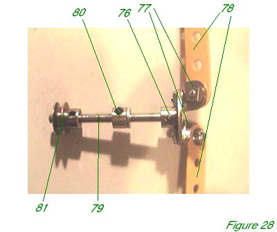

Figure 28 shows the airscrew in isolation. A 1" bush wheel 76 (Electrikit part 518 - a very useful part, well worth buying) carries two obtuse angle brackets 77. A washer is placed between bracket and bush wheel to prevent the bracket being fouled by the peening of the boss. Two 5 1/2" perforated strips 78 are bolted to brackets 77 for the blades of the propeller. Bush wheel 76 is fixed to a 2 1/2" axle rod 79.
This will be journalled in the flanged plate and double bent strip previously mentioned and secured in place by a collar 80. A 1/2" pulley 81 is secured to axle rod 79. A small rubber pulley (part 23c) on the motor shaft carries the drive to pulley 81 using a 2 1/2" driving band.

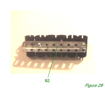
Figure 29 shows the engine block. This simple construction has six 1 1/2" sleeve pieces bolted together at the bases in a line, through the lowest of the three holes in each sleeve piece, with a washer between each sleeve piece, using a screwdriver narrow enough to pass through the opposite hole before it too is secured - or, of course, an Allen key and Allen bolts, as in the model.
The sleeve pieces must be arranged so that some have the open side facing right, and some have the open side facing left. Furthermore, they must be arranged so that a 4 1/2" girder 82 can be bolted to the upper of the two holes on the closed side on at least one sleeve piece on each side. In the model the left girder is bolted to the third cylinder from the front, while the right girder is bolted to the first and fifth cylinders.

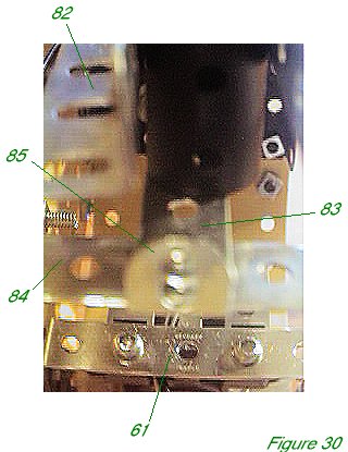
A 4 1/2" perforated strip 83 connects the angle bracket in flanged plate 65 to the double angle strip 84 nine holes back. This strip acts as a base for the engine block. A second 1/2" x 1/2" angle bracket 85 is attached to the centre of double angle strip 84. Figure 30 shows the engine block in place with the final sleeve piece removed for clarity. The final sleeve piece is bolted to the preceding sleeve piece, and to the slot of angle bracket 85 using a 1/2" long bolt, with a rubber pulley between bolt and sleeve piece as a tight cushion.
Girders 82, besides helping to hold the sleeve pieces in place, also model two steel channels which were supposed to protect the engine block from stray bullets, in the original aircraft.
The engine block is bolted in place at the front using 1/2" long bolts and rubber pulleys as cushions, according to the instructions in the previous "Fuselage Framework" section. Tighten the lower bolt first, of course, and then the upper bolt.
INTRODUCTION | PARTS LIST
CONSTRUCTION: Upper Wing | Undercarriage | Fuselage Framework | Airscrew and Engine Block | Cockpit and Joystick | Lower Wings | Fuselage Covering and Wing Struts | Guns and Tailplane |
POSSIBLE IMPROVEMENTS