A Meccano Dinosaur
by Paul Dale
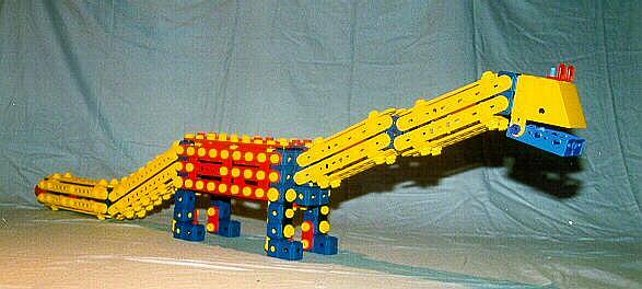

by Paul Dale

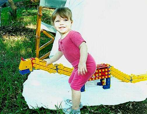
This dinosaur was designed and built to provide my then two year old daughter with something to play with. It proved very successful and I've rebuilt it several times since its original creation. The current rebuild has survived over a year of "play" with (now) several children, and only an occasional tightening of bolts being required. This despite regular riding and generally rough treatment.
This model has been previously described and published in the Johannesburg Meccano Hobbyists Newsletter, January 2001, Volume 5 Number 3.
The body is a box with three nine hole Flat Strips along each side, four across the top and a pair mounted centrally underneath. The four Flat Strips on top are raised by a crosswise four hole Flat Strip at each end and the central pair of nine hole Flat Strips are raised again by a Plate at each end. These two Plates overlap and are bolted to the head and tail end Square Blocks to provide additional support. A two hole Flat Strip acts as spacing between the Square Block and the Plate in each case. A pair of seven hole Flat Strips lie underneath the central pair of nine hole Flat Strips along the top providing extra support and acting as spacers for the internal bracing. Inside the body, the sides and top are strengthened using a variety of flat parts and pairs of Double Blocks and Square Blocks. These latter blocks join the sides and the tops together. The more bracing here the better, although more than one layer is probably unnecessary.
The front and back of the body are both constructed in much the same manner. A Square Block is attached to a Double Block and both sides of these joined using Triple Blocks making a four hole by three hole compound plate. All internal holes are connected using Locking Pins. The front has an extra Double Block bolted below where the neck assembly attaches. The Double Block is bolted to the underside of the Square Block that forms the lower end of the neck.
Fig 1: Front of body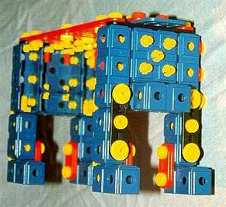
Fig 2: Rear bottom of body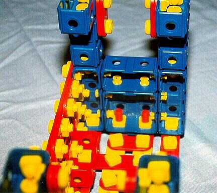
Fig 3: Inside of body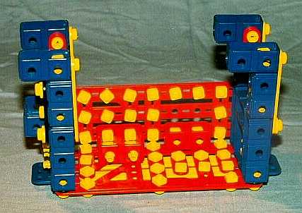
Fig 4: Under view
Each leg is built from a pair of Double Blocks bolted together in an 'L' shape. These are bolted to each corner of the body. The inside of each leg has a pair of two hole Flat Strips connecting the two Double Blocks together. The rear of each leg has a four hole Flat Strip bolted to the lower Double Block and the strips on the rear leg are also bolted to the rear of the body. The front legs are joined to the front of the body using three hole Flat Strips.
The neck is constructed next. It is made up of two box sections connected end to end by their sides using a pair of Plates. Each box section is similar, being built from two pairs of seven hole Flat Strips at the sides and two pairs of six hole Flat Strips forming the top and bottom. The sides are strengthened and properly angled by bolting a Triangle piece to each side of both box sections. Both pairs of tops and bottoms are attached to the sides of the box section using a pair of Short Double Brackets. The ends of the neck section consist of Square Blocks bolted to the sides of the box sections. These two Square Blocks attach to the body and head using Locking Pins in all available holes.
Fig 5: Neck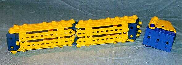
Fig 6: Inside of neck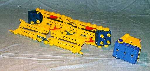
The head is built from a Large Angle Block with a pair of three hole Flat Strips which hold the lower jaw in position. The lower jaw is made from a blue Base which is lock nutted in position. An alternative lower jaw can be made using only current part eg. two Triple Cubes bolted together. The head is decorated with a pair of old style Angle Brackets. The recent narrow Angle Bracket would make for an ideal substitute here. A pair of the green rubber push in eyes can be added, however they do fall out easily when being handled by children and I soon left them out. The head unit is connected to the Square Block at the upper end of the neck by four Locking Pins in the rear of the Large Angle Block.
The tail section is again constructed from two box sections. The lower box section sides are pairs of nine hole Flat Strips and its top and bottom are both made from another pair of nine hole Flat Strips. The sides of this box section are braced using a Short Corner in the middle of each side. A pair of Triangles is used to produce a taper effect at the end of the tail. As in the construction of the neck, the top and bottom pairs of strips are attached to the sides using pairs of Short Double Brackets. The upper box section is constructed in a similar manner, again using nine hole Flat Strips for the sides. The top and bottom pairs of strips are eight holes long with each being built from two four hole Flat Strips butt joined using a third four hole Flat Strip. The two halves of the tail are joined together by a pair of Squares. The upper box section has no side bracing as the tail is simply allowed to rest on the ground. If bracing is desired, a pair of Triangles produces almost the correct angle. The upper end of the tail is bolted to a Square Block which attaches to the body using five Locking Pins.
Fig 7: Tail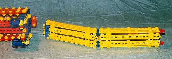
Fig 8: Inside of tail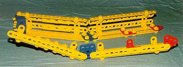
The current range of block pieces has introduced parts with integral threaded holes and the Locking Pins are now half threaded. Using these more modern parts will require some alterations to the construction. It should also possible to replace many of the Locking Pins with Bolts which should increase the strength of the neck and tail joints. Many bolts also need washers under their heads for spacing purposed.
Here is a list of the required parts to build the model as pictured and described above:
| Part | Description | Quantity |
|---|---|---|
| J2 | Flat Strip 2 holes | 13 |
| J3 | Flat Strip 3 holes | 4 |
| J4 | Flat Strip 4 holes | 18 |
| J6 | Flat Strip 6 holes | 8 |
| J7 | Flat Strip 7 holes | 10 |
| J9 | Flat Strip 9 holes | 24 |
| J51B | Bolt | 254 |
| J51N | Nut | 260 |
| J53 | Washer | 44 |
| J54B | Pivot Bolt | 6 |
| J56 | Locking Pin | 32 |
| J121 | Double Cube | 13 |
| J122 | Square Block | 7 |
| J131 | Triple Cube | 4 |
| J234 | Large Angle Block | 1 |
| J432 | Short T | 2 |
| J531 | Short Double Bracket | 16 |
| J622 | Short Corner | 4 |
| J632 | Long Corner | 4 |
| J633 | Corner Brace | 2 |
| J822 | Plate | 6 |
| J922 | Triangle | 6 |
| J942 | Flat Double Bracket | 2 |
| P54 | Base | 1 |
| P55 | Bolt 19mm 3/4" | 2 |
| P56 | Bolt 25mm 1" | 2 |
| P57 | Nut | 4 |
| P59 | Angle Bracket | 2 |
HTML web page plus illustrations (dinohtml.zip, 249K)
Select the link to download the file "dinohtml.zip". Save the ZIP file in a new directory, and use your favourite "unzip" program to extract the files, then open the file "index.htm" in your browser to view this web page offline. This version has been set to black text on a white background to make printing easier.
Text file plus the image files (dinotext.zip, 244K)
Select the link to download the file "dinotext.zip", which contains a single text file (dinotext.txt) plus the image files containing the illustrations used in these pages. Save the ZIP file in a new directory and use your favourite "unzip" program to extract the files. You can then print out the text file which contains the model notes, and view/print the images using your browser or your favourite graphics program.
These instructions and the accompanying pictures are copyright material (belonging to Paul Dale), and all rights are reserved. They are made freely available to Meccano modellers on condition that they are not copied and distributed in any form for sale, whether or not the sale is for profit or merely 'at cost'. Nor may they be distributed in incomplete form. Printed copies may however be made freely for personal use.